Mechatronics · 2026
Whiteboard Drawing Robot
Designing a compact SCARA-style robot to reproduce uploaded sliced or vector paths on a whiteboard. The mechanical system has been fully designed in Onshape, printed, mostly assembled, and the stepper motors have been installed, wired, and tested.
- Role
- Independent Design Project
- Tools
- Onshape, 3D Printing, Arduino, NEMA 17 Stepper Motors, DRV8825 Drivers
- Timeline
- In Progress
- Team
- Individual Project
01Objective
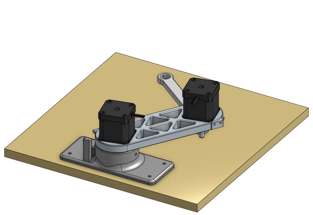
The goal of the project is to create a compact robot capable of reproducing uploaded sliced or vector paths on a whiteboard.
The system is designed around a roughly 200 × 150 mm drawing workspace and uses a two-joint SCARA-style arm to position a marker across the board.
02My role
This is an independent project. I designed the full mechanical assembly from scratch in Onshape and am responsible for the mechanical design, fabrication, electronics integration, motion control, and eventual path-processing workflow.
- Designed the complete SCARA-style mechanical assembly
- Designed all custom 3D-printed structural components
- Developed the marker-holder and drawing mechanism
- Selected and installed the stepper motors and motor drivers
- Completed stepper motor wiring and initial motion testing
- Planned the homing and motion-control architecture
- Designed the system around a compact 200 × 150 mm workspace
03Mechanical design
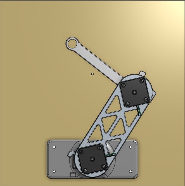
The robot uses a two-link SCARA-style arm to position a marker across the drawing surface. I selected this architecture because it provides a relatively large planar workspace with a compact mechanical footprint.
The structural components were designed for 3D printing, allowing the project to be fabricated inexpensively while still supporting rapid iteration.
The marker mount was designed with vertical compliance so the marker can maintain contact with the whiteboard despite small surface or assembly variations.
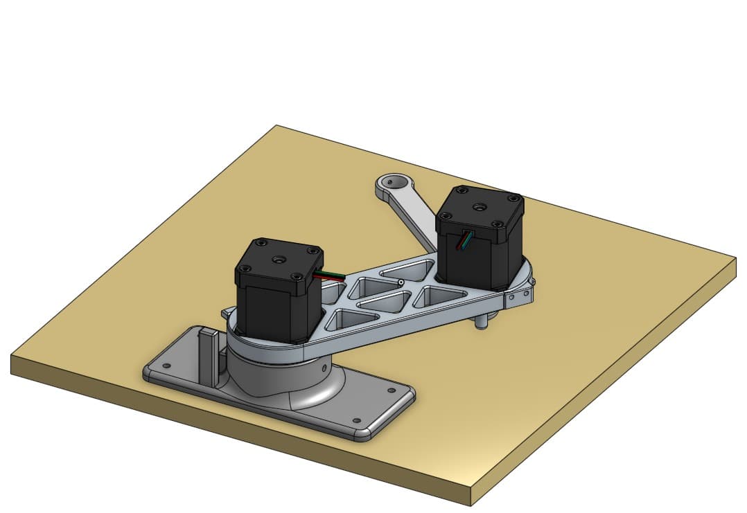
The CAD model was used to define the arm geometry, workspace, motor placement, joint interfaces, and printed components before fabrication. Designing the full assembly digitally allowed interference and packaging issues to be addressed before printing.
04Electronics & motion system
The arm is driven by two NEMA 17 stepper motors controlled through DRV8825 stepper drivers. An Arduino serves as the primary motion controller using STEP/DIR signals.
The stepper motors have been installed, wired, and individually tested. This verified the basic motor-driver setup and established the foundation for coordinated two-axis motion.
The next electronics milestone is wiring the limit switches so the robot can establish a repeatable home position before beginning a drawing.
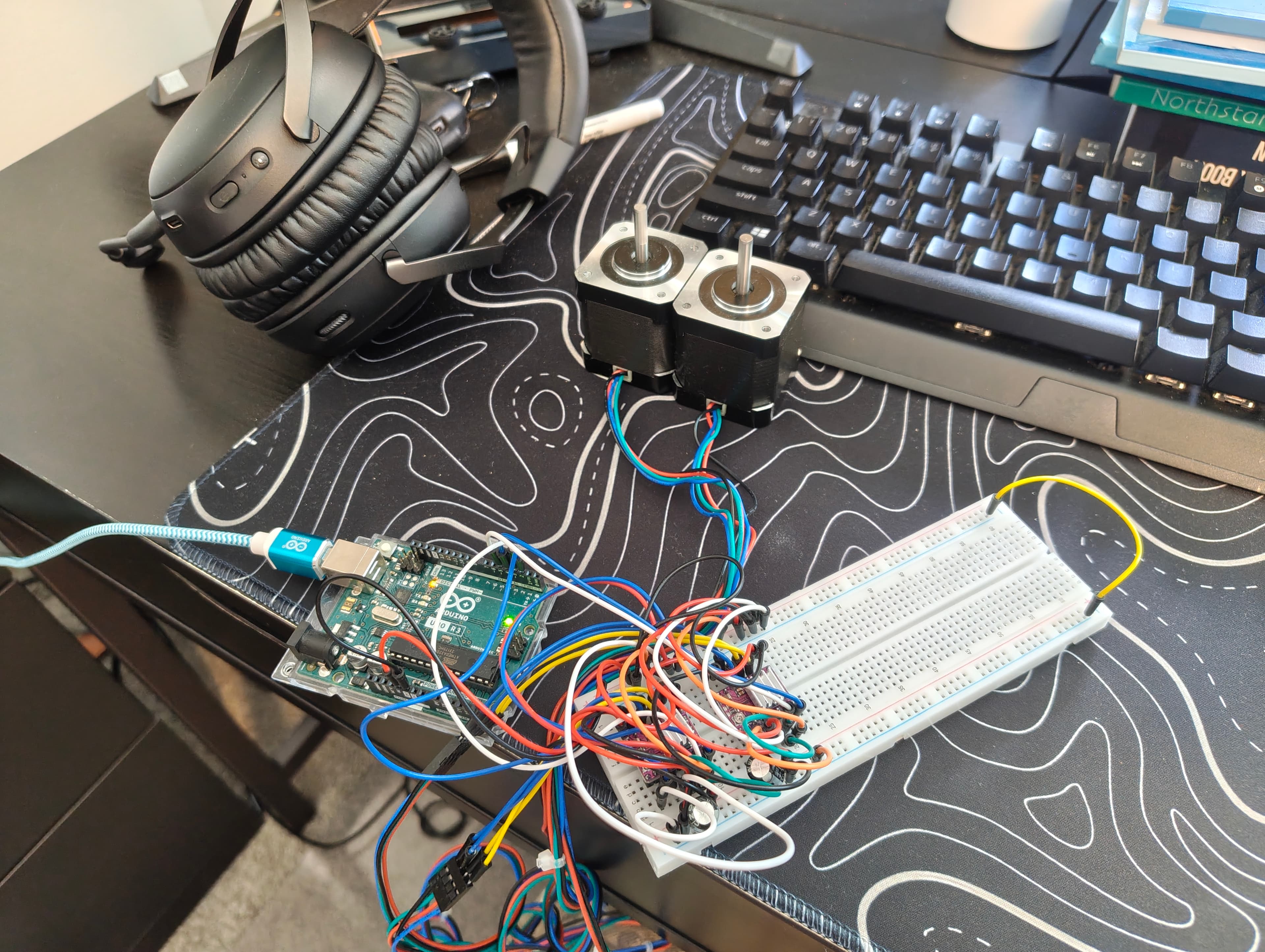
The motor wiring and driver setup are complete, and both stepper motors have been tested. The limit switches have not yet been wired.
05Motion architecture
The planned control system will convert uploaded path data into XY positions, use inverse kinematics to determine the required joint angles, and command the two motors to reproduce the path on the whiteboard.
Two limit switches will be used for homing so the robot can establish a known reference position before executing a drawing.
06Current progress
The mechanical design is complete and the custom components have been 3D printed. Most of the mechanical assembly has also been completed.
The stepper motors are installed, the motor wiring is complete, and both motors have been tested. The remaining electronics work includes wiring the limit switches and completing the homing setup.
The project is now transitioning from basic hardware bring-up into coordinated motion control, homing, calibration, and path execution.
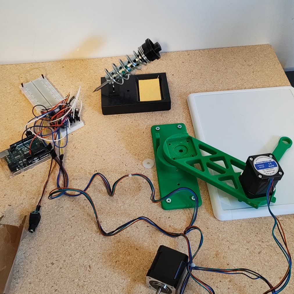
With most of the mechanical assembly complete, the next phase is focused on integrating homing and coordinated two-axis motion before beginning path-following tests.
07Next steps
- Wire and test the limit switches
- Implement repeatable homing
- Develop inverse-kinematics control for XY positioning
- Coordinate both stepper motors during planar motion
- Convert uploaded sliced or vector paths into motion commands
- Calibrate the arm for drawing accuracy
- Validate the system using simple shapes before progressing to more complex paths
08Fabrication
09Project status
- Status
- In Progress
- Workspace
- ~200 × 150 mm
- Architecture
- 2-DOF SCARA
- Actuation
- 2 × NEMA 17
- Motor Drivers
- DRV8825
- CAD
- Onshape
10Planned outcome
The immediate goal is to achieve repeatable homing and coordinated two-axis motion, followed by successful reproduction of a simple uploaded path. From there, the focus will shift toward calibration, drawing accuracy, and support for progressively more complex paths.