Mechanical Design · 2026
3D-Printable Cycloidal Gearbox
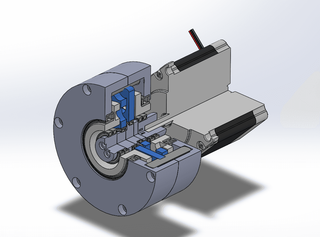
Designed a compact 17:1 cycloidal reduction gearbox around an 18-pin stationary ring and 17-lobe cycloidal disk, with an emphasis on compact packaging, bearing integration, and manufacturability through 3D printing.
- Role
- Independent Design Project
- Tools
- SOLIDWORKS, Mechanical Design, Cycloidal Drive Design, 3D Printing
- Timeline
- Design Complete
- Team
- Individual Project
01Objective
The goal of this project was to design a compact cycloidal gearbox capable of achieving a relatively high reduction ratio while keeping most custom components suitable for additive manufacturing.
A cycloidal architecture was selected because it allows a large reduction to be achieved in a single stage while maintaining a compact overall package.
02Design approach
The gearbox was designed around a stationary outer ring containing 18 pins and a 17-lobe cycloidal disk, producing a nominal 17:1 reduction ratio.
An eccentric input drives the cycloidal disk through its orbital motion, while the reduced rotation is transferred through the output mechanism to a concentric output shaft.
03Cycloidal geometry
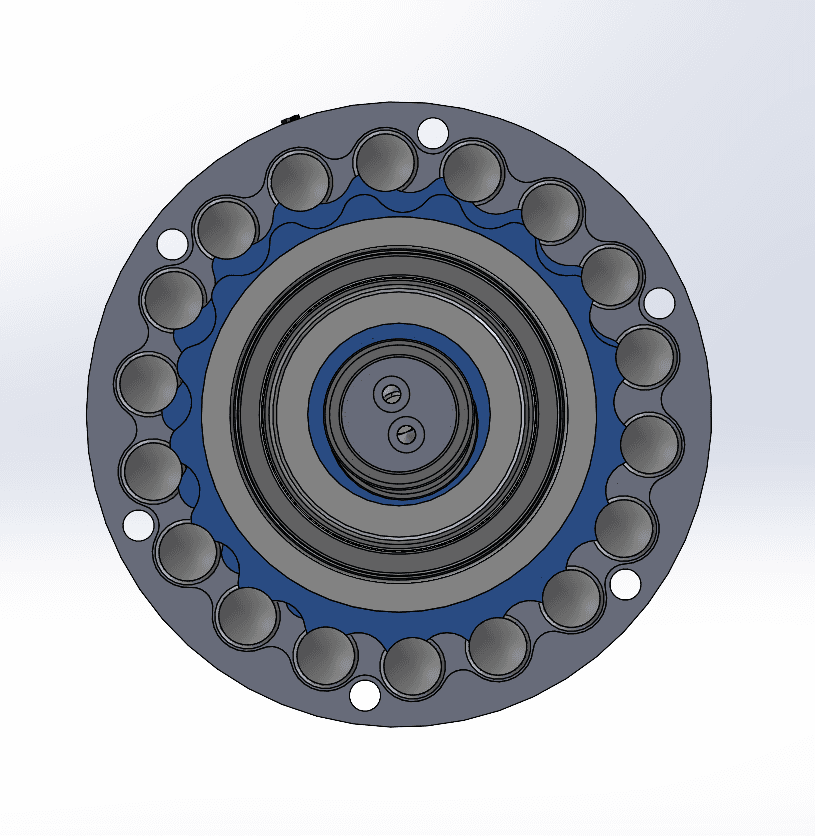
The reduction stage uses an 18-pin stationary ring surrounding a 17-lobe cycloidal disk. As the eccentric input rotates, the disk moves eccentrically against the fixed pins while slowly rotating in the opposite direction.
Because the ring contains one more pin than the cycloidal disk has lobes, each complete input revolution advances the disk by only a small angular amount, producing the 17:1 reduction in a single stage.
04Internal architecture
The assembly was packaged concentrically around the input and output axes, with the eccentric drive, cycloidal disk, output mechanism, and supporting bearings contained inside the outer housing.
A major part of the design process was fitting the reduction stage, bearings, shafts, fasteners, and output components into a compact package while maintaining sufficient clearance for the eccentric motion of the cycloidal disk.
05Exploded assembly
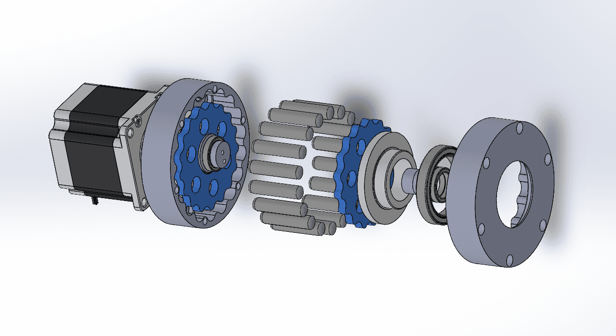
The gearbox was designed as a layered assembly centered around the motor input, cycloidal reduction stage, eccentric mechanism, output components, bearings, and surrounding housing.
The exploded view shows how the major components stack axially and how the reduction stage is packaged within the enclosure.
06Bearing and output system
The design uses bearings to support the eccentric input, rotating output components, and major load-carrying interfaces. Bearing locations were incorporated into the overall architecture early in the design rather than added after the surrounding geometry was complete.
The output mechanism transfers the slow rotation of the cycloidal disk to a concentric output while still allowing the disk to undergo its eccentric motion.
07Design for 3D printing
The gearbox was intended to use 3D printing for most of its custom geometry while relying on standard hardware for components such as bearings, shafts, pins, motors, and fasteners.
This required balancing compact packaging with practical wall thicknesses, bearing seats, fastener access, assembly clearance, and the dimensional limitations associated with FDM printing.
08Design considerations
- Achieve a 17:1 reduction within a compact single-stage package
- Keep custom components practical to manufacture through 3D printing
- Support the eccentric and output assemblies with appropriate bearing locations
- Maintain sufficient clearance for the cycloidal disk's eccentric motion
- Package standard bearings, pins, shafts, and fasteners into the printed structure
- Keep the assembly reasonably accessible and serviceable
09Project status
The mechanical design and CAD assembly were completed, but the gearbox was not fabricated. Because of this, backlash, efficiency, load capacity, thermal behavior, and long-term durability have not been experimentally validated.
The project currently represents a completed mechanical design study rather than a tested gearbox.
10Next steps
- Fabricate the gearbox and verify assembly tolerances
- Confirm smooth operation across a full input revolution
- Measure backlash at the output
- Evaluate efficiency and load capacity
- Inspect printed components for wear or deformation
- Revise clearances and component geometry based on testing